Mechanical Design
Unlike previous class projects, most hardware hardware was not provided, or even specified. This gave us the opportunity to design the entire system from the ground up. The Nucleo L476, motor drivers, and motors were made available to us by our instructor, guiding some design decisions, but the rest was up to us.
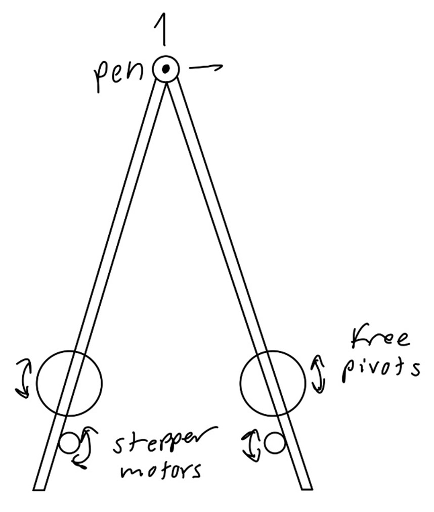
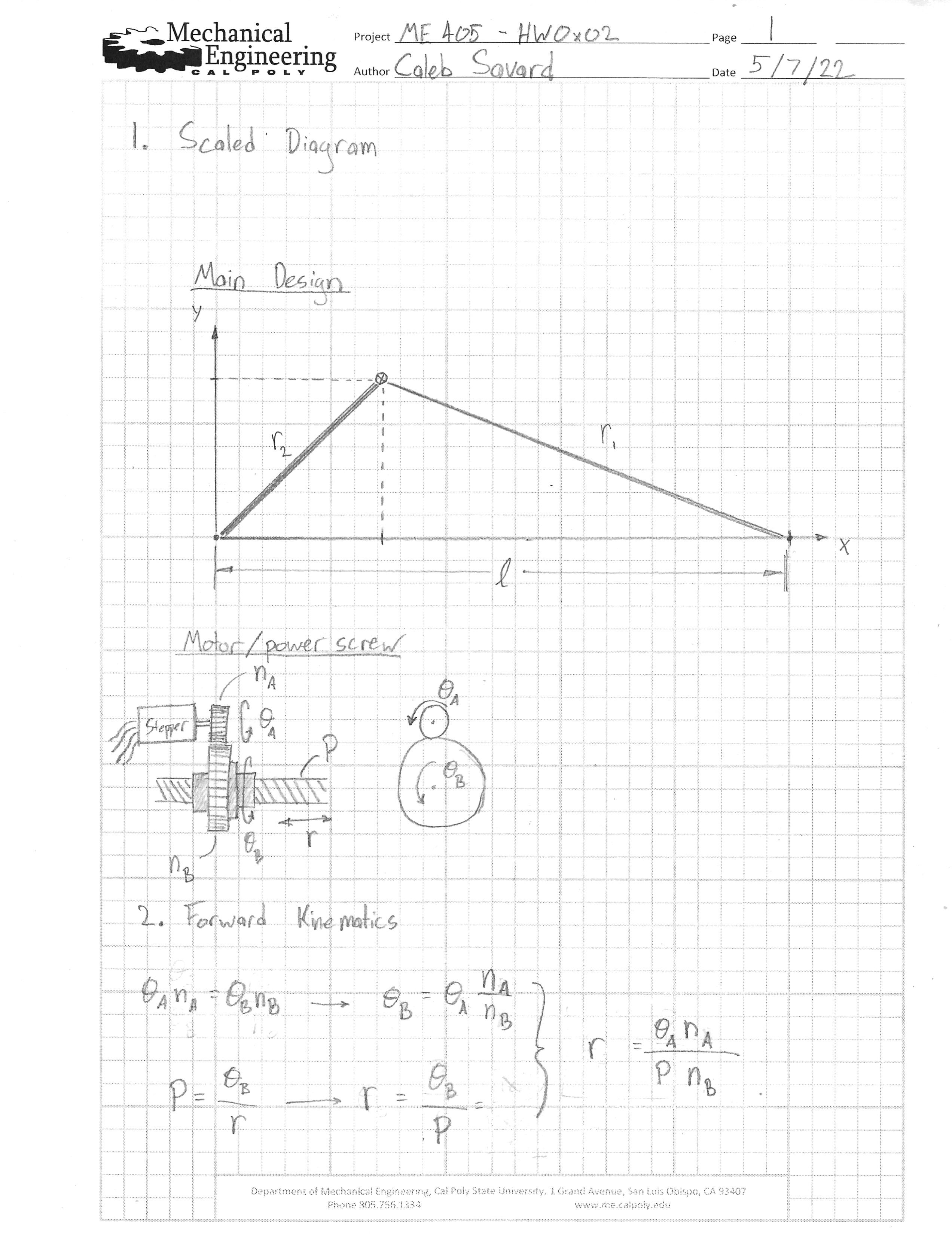
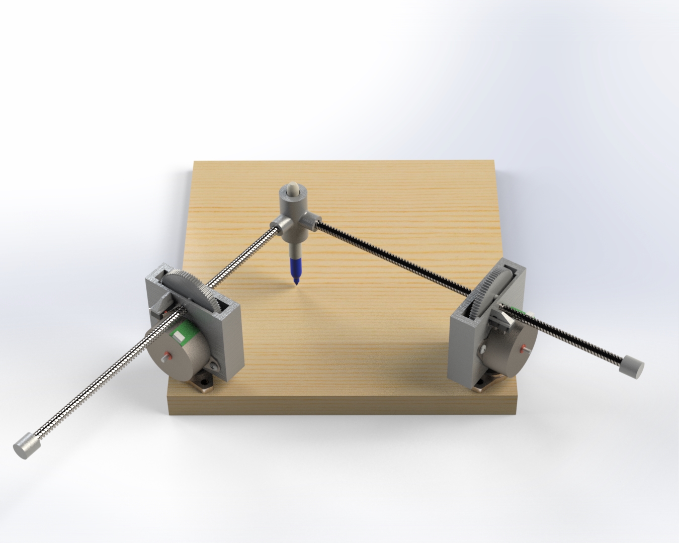
Inspired by similarly designed 3D printers, we quickly decided on a triangulating design, where two ‘arms’ are allowed to pivot freely, locating the pen by their different lengths.
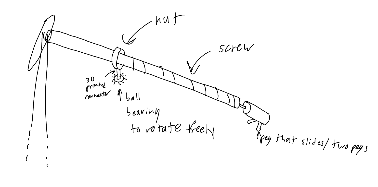
We considered a number of different ways to control the length of the arms. We thought of power screws, but balked at the complexity of driving the shaft, while still maintaining a stable connection to the static pen.
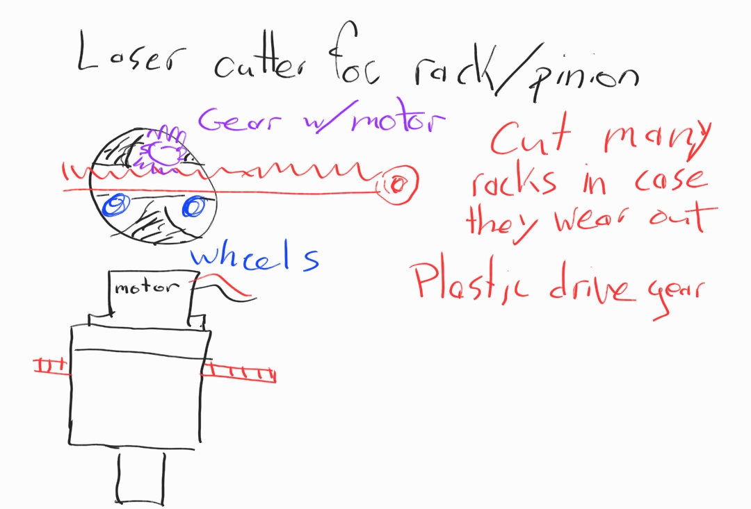
A rack and pinion seemed like a good option since the rack doesn’t rotate, but it posed a significant manufacturing challenge and could incur too much slop.
We also considered a smooth rod with rubber rollers, but were concerned with slipping. Finally, we found a way to blend the best of these ideas into one using a power screw, but instead of rotating the shaft, we planned to rotate the nut.
Analysis
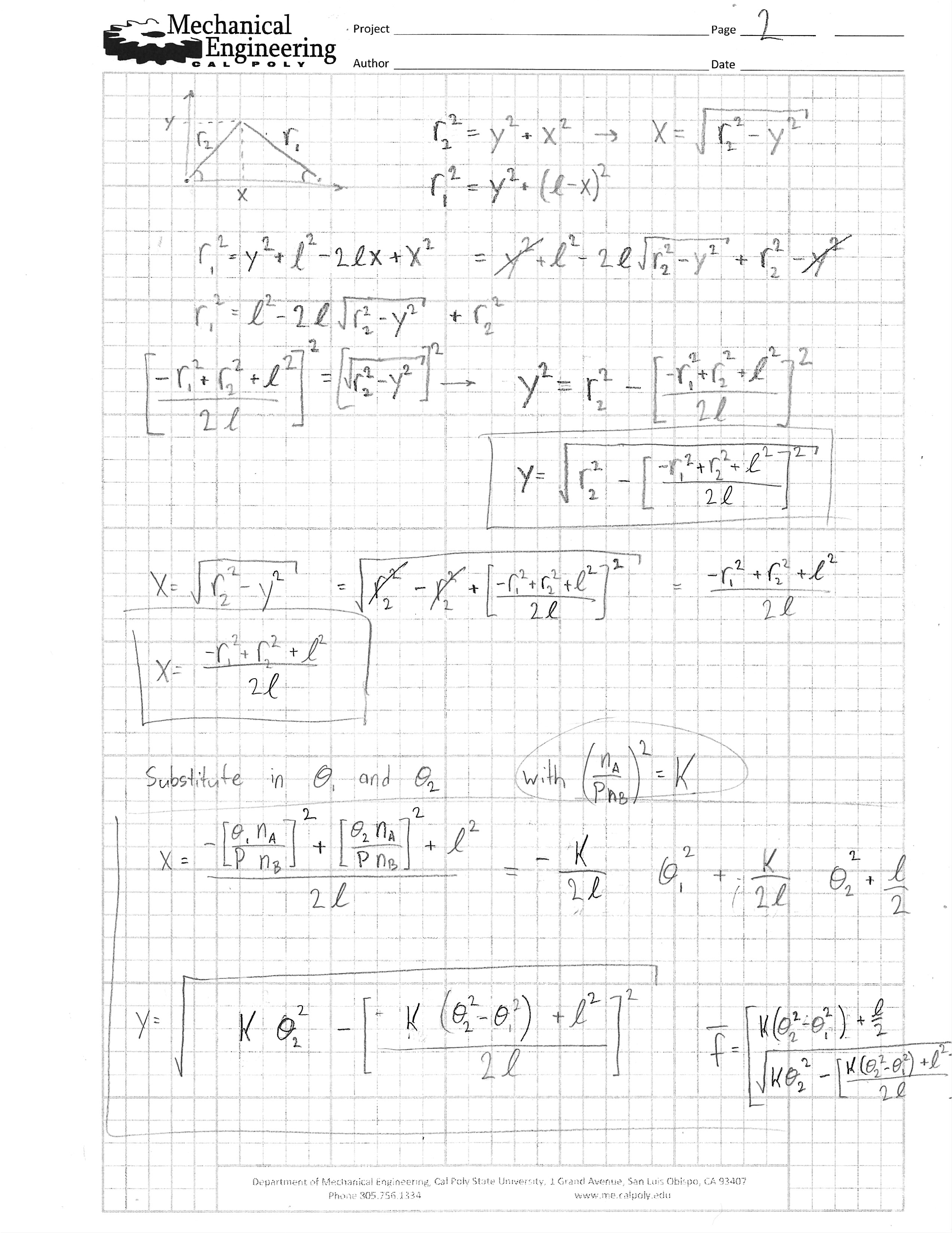
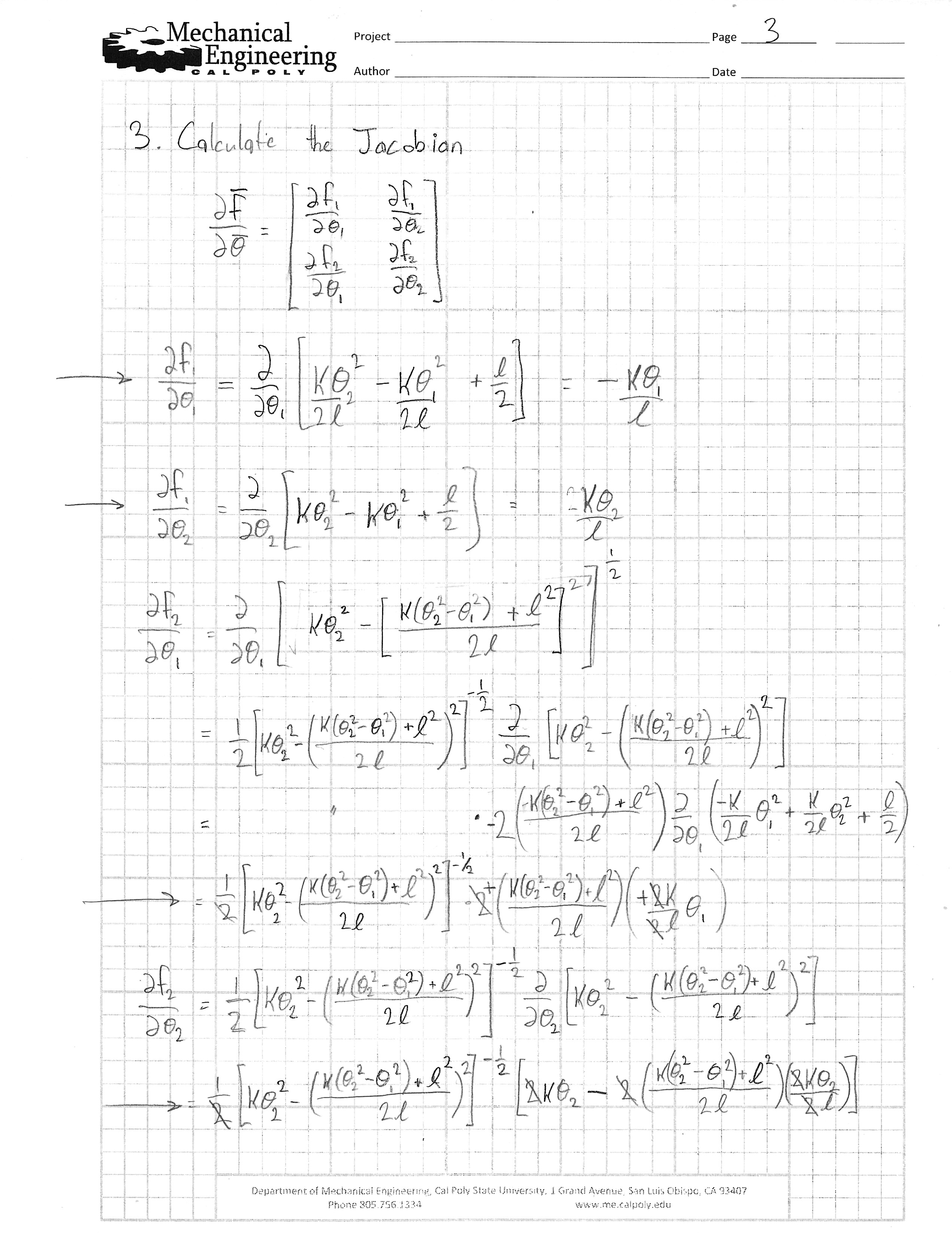
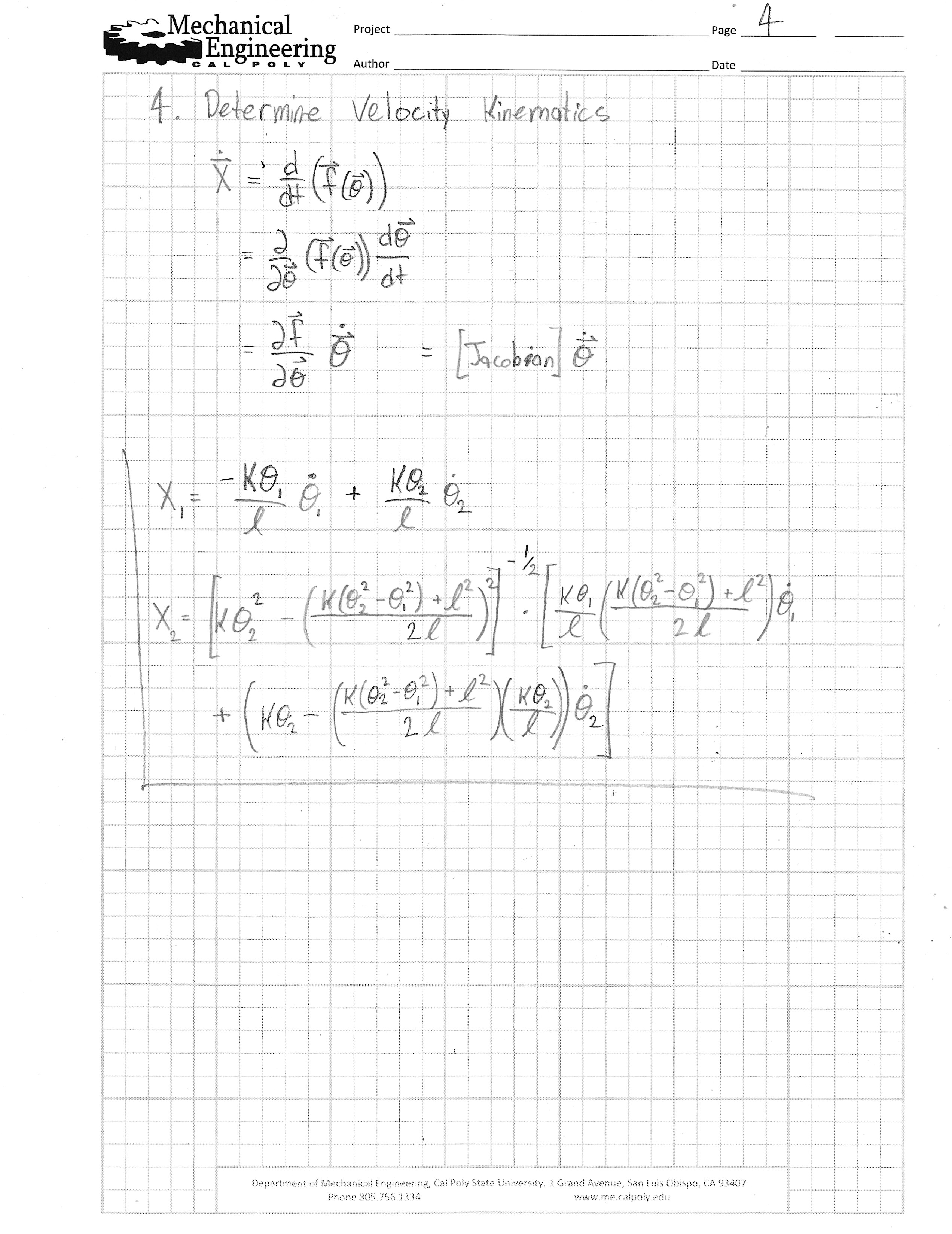
The bulk of the math involved for this project was in the kinematics. Getting from arm lengths to X Y coordinates was straightforward, but going back the other way is not. Fortunately, the Newton-Raphson algorithm can help with this, iteratively applying input values to the forward kinematics until X Y outputs reach the target. More information on this algorithm can be found in the Data Task, but the building blocks (forward kinematics and the jacobian) are derived below.
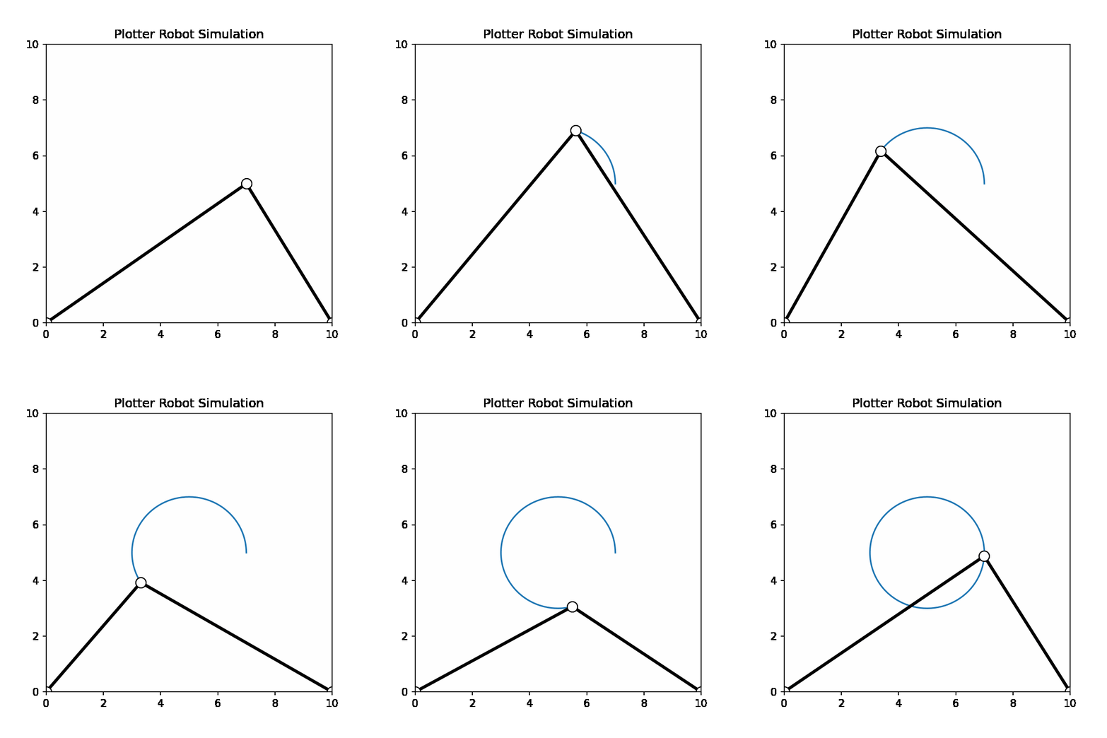
To ensure that the Newton-Raphson approach would work, we simulated the system using Jupyter. The Newton-Raphson algorithm was applied to the points in a circle, then the forward kinematics were solved to get the resulting X Y points. As shown in the animation below, the results were nearly perfect.
CAD
The majority of the components were first modeled in SolidWorks to ensure correct fitment. This made the 3D printed parts easy to design, since their dimensions could be defined by referencing other parts.
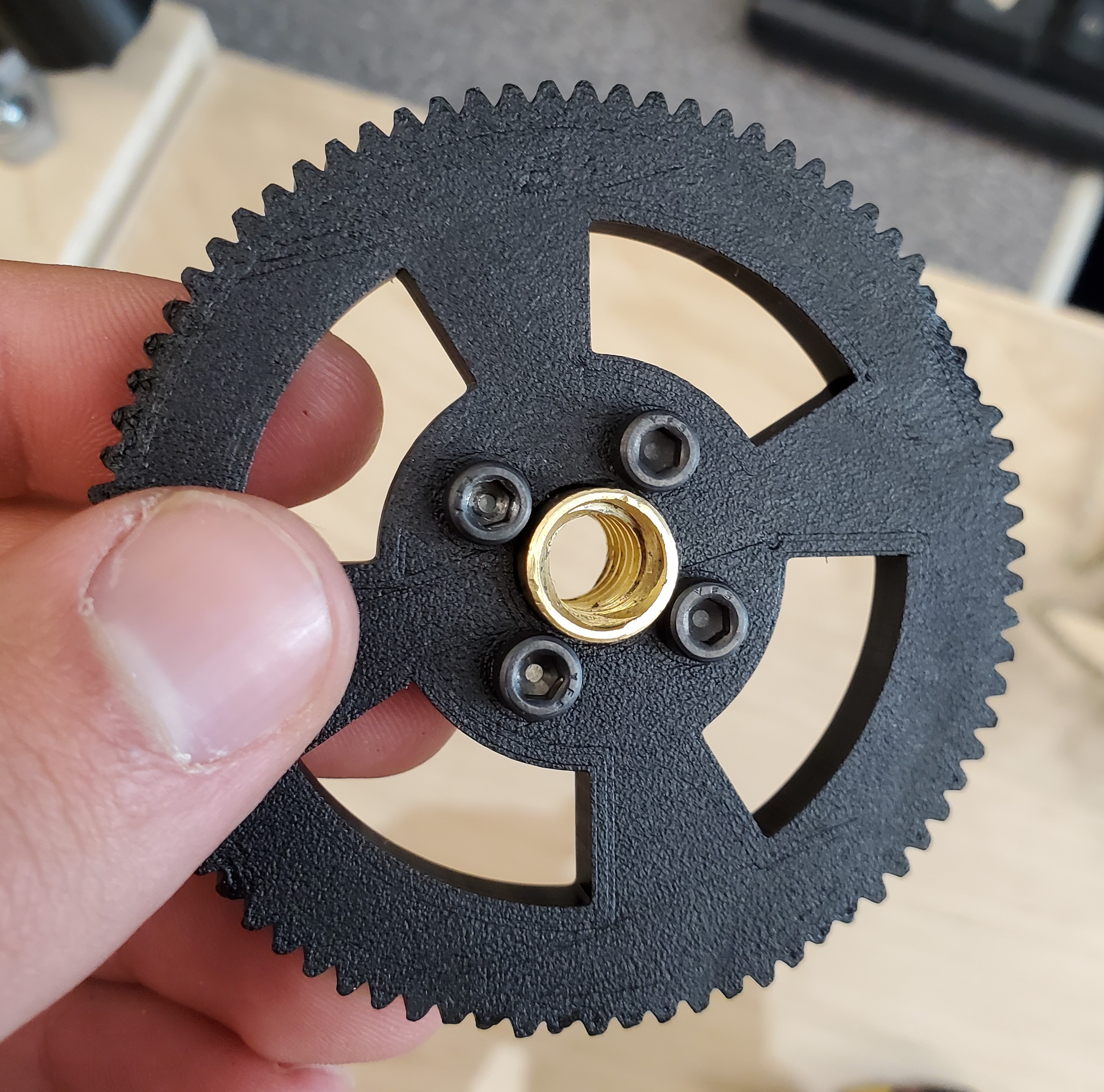
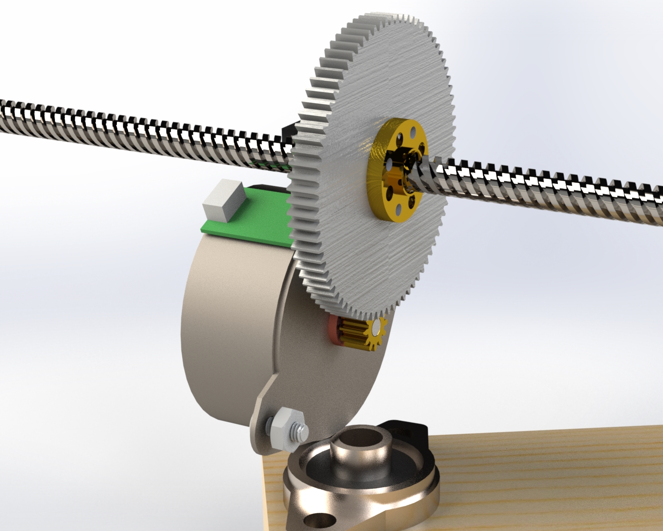
The gear was designed using the SolidWorks toolbox to fit neatly over the power screw nut and mesh with the original gear on the stepper motor.
The SolidWorks files from this project are included in the link below.
Manufacturing
BOM
Nucleo L476 Microcontroller
PM25S-048 Stepper Motors (2)
- Motor Driver circuitry
TMC2208 Stepper Drivers (2)
TMC4210 Step/Direction Controllers (2)
Miscellaneous electronics parts
- 3D Printed Parts
Support Connector (2)
Large Gear (2)
Lower Pen Connector
Upper Pen Connector
End Connector (2)
6-32 3/8 machine screws, Socket head (8)
8-32 1/4 machine screws (4)
8-32 nuts (4)
1/2 in Pan-head wood screws (4)
3/8 in Plywood
Motor Driver Board
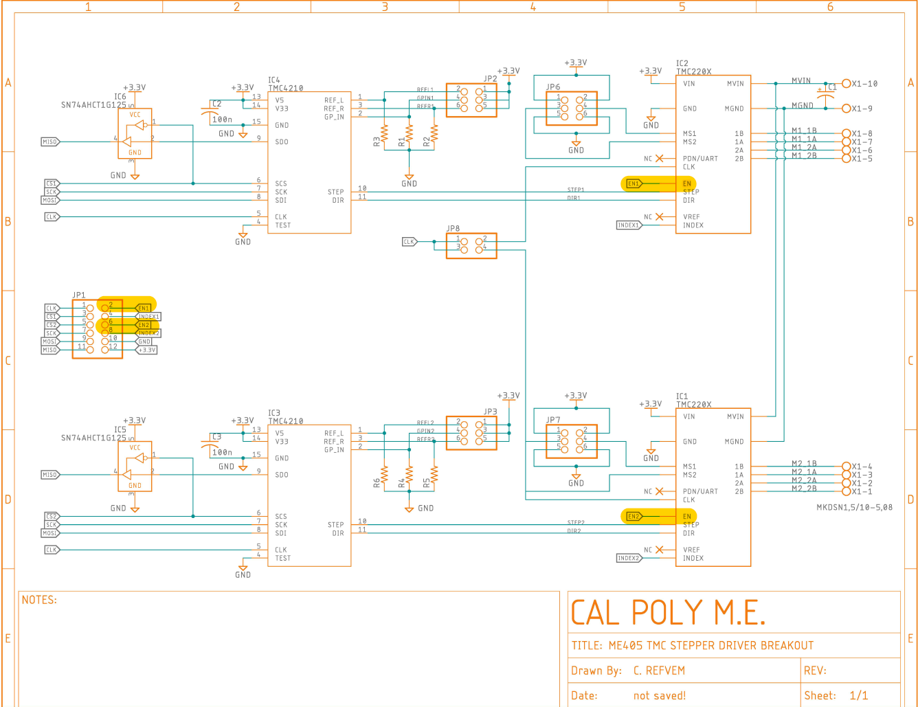
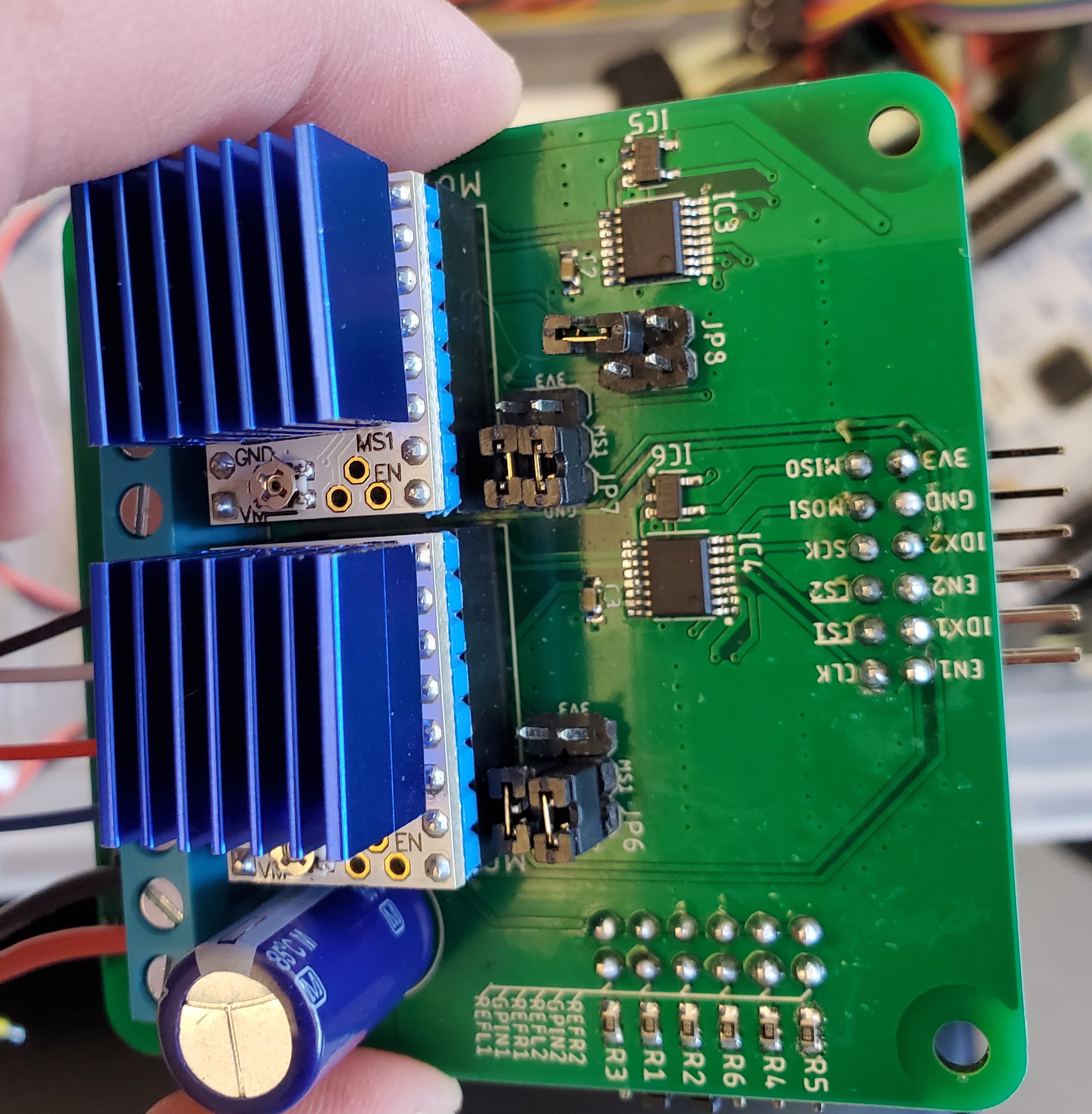
A motor driver PCB was also provided with an two integrated TMC4210 Step/Direction controllers and pin headers for standard stepper motor drivers (TMC2208 in this case).
Motor Modification
While some teams chose to purchase their own stepper motors, we decided to use the ones made available by our instructor. They appear to be 5- and 6-wire variants of the NMB PM25S-048, likely surplus or refurbished condition. Because our driver is for 4-wire steppers, the motors would need to be modified.
5- and 6- wire stepper motors have a connection between the two phases of the motor to simplify the driving circuitry. For these 4-wire drivers, this connection must be broken. One option was to de-solder the PCB mounted to the motor and attach leads directly to the coils, omitting the central ground on each. We preferred to retain the convenient plug mounted to the PCB, so we opted for cutting the trace on the PCB itself.
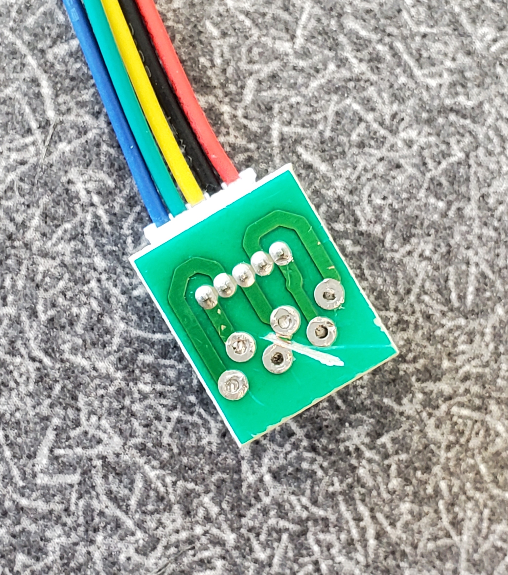
On these motors, the connecting trace was found on both the top and the bottom of the board, so desoldering it from the stepper motor was required.
Power Screw Modifications
Unfortunately, the mounting holes on the powerscrew nut were so close to the center that the screw heads interfered with the center barrel. To remedy this, we drilled and tapped new, smaller holes, further from the center, and used socket-head screws for their smaller head diameter.
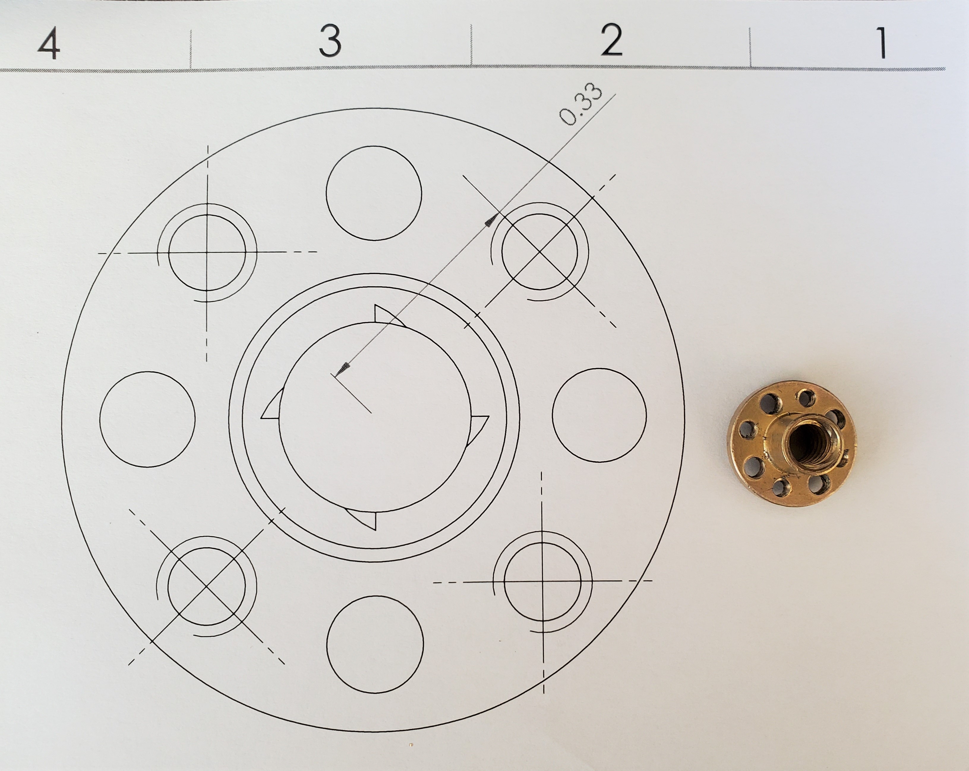
This modification was enough to allow the screws to fit. We were concerned that the smaller shoulder on these tiny screws would be detrimental to the 3D printed gear, but this turned out to be unfounded.
